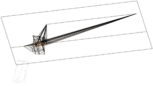
1 A three dimensional object is projected onto a picture plane. |
|

2 A Distance Point perspective of the object is constructed on the picture plane. |
|

3 One surface (shaded) of the Distance Point perspective is projected onto a rotated plane. The rotated plane intersects the surface on the object of which the shaded surface is a perspective. The intersection corresponds to the ground line of the Distance Point perspective. |
|

4 The object and intersecting shaded surface are rotated 90 degrees to the picture plane. The rotated view is projected back onto the picture plane. On this picture plane, the projected view, together with the original two dimensional view and perspective, describes the three dimensional position of the shaded surface as it intersects the object. |
|

5 The two dimensional description of the three dimensional shaded surface provides the basis for constructing a third dimension for the rest of the perspective. Two dimensional stereometric projections attached to the shaded plane establish the rest of the third dimension. |
|

6 The picture plane is folded such that the two views defining a three dimensional object are 90 degrees to one another. |
|

7 The stereometric view and perspective are projected to construct a three dimensional object. |
|

8 The new perspective object is moved to join with its shaded plane -- because that plane binds it to the original object. |
PRESSO VILLA MARCO III 1994 |

9 |
 |

10 |
 |

11 |
 |

9–12 A second Distance Point perspective is inflated into three dimensions; the resulting objects interlock and intersect with the original object and the first perspective object. |
 |
projects | 1
| 2
| 3
| 4
appendx inc.©1997